
Page 229 - Demo
P. 229
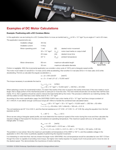
V012024 • © 2024 Portescap. Specifications subject to change without notice.Examples of DC Motor CalculationsExample: Positioning with a DC Coreless Motor.In this application we are looking for a DC Coreless Motor to move an inertial load (Jload) of 40 × 10-7 kgm2 by an angle of 1 rad in 20 msec.The application requirements are:Available voltage: 48 VdcAvailable current: 4 AmpMotor operating point: 1 rad [Ø] desired motor movement30 × 10-7 kgm2 [Jload] motor load inertia on output shaft20 msec [∆t] desired move time22° C [Tamb] ambient temperatureMotor dimensions: 68 mm maximum allowable length35 mm maximum allowable diameterFriction is negligible. With this incremental application we consider a duty cycle of 100% and a triangular speed profile.The motor must rotate 0.5 rad (Ø/2) in 10 msec (∆t/2) while accelerating, then another 0.5 rad (also Ø/2) in 10 msec (also ∆t/2) while decelerating. First let us calculate the angular acceleration α. α = (2 × Ø/2 )/(∆t/2)2 [rad/s2] α = 2 × .5 rad/ (.01 s)2 = 10,000 rad/s2The torque necessary to accelerate the load is: τload = Jload × α [mNm] τload = 30 × 10-7 kgm2 × 10,000 rad/s2 = .030 Nm = 30 mNmWhen selecting a motor for incremental motion, it is best if the inertia of the rotor is equal to the inertia of the load. If the rotor inertia is much larger, then a large portion of the mechanical power is used just to move the rotor. The rotor inertia should also not be less than half the load inertia. If it is, then a gearbox should be used to reduce the load inertia felt by the motor. This process is referred to as matching inertias. We will thus select a motor that has a rotor inertia close to 40 × 10-7 kgm2.According to the motor specification page, the 30GT2R82-234P.4 has a rotor inertia of 33 × 10-7 kgm2 and has a torque constant of 20.1 mNm/A. It can deliver enough continuous torque (87 mNm) to handle the combined load calculated below. τrotor+road = (30 × 10-7 kgm2 + 33 × 10-7 kgm2) × 10,000 rad/s2 = .063 Nm = 63 mNmI = τ / k + I0 = 63 mNm / (20.1 mNm/A) + 180 mA = 3.31 AThe coil resistance (at 22° C) is 0.50 Ω, and the thermal resistance is 4.5° C/W + 9° C/W / 2 = 9° C/W. By using the equation from the first example we find: TF = 83° C R83° C = .62 ΩSince we are using a triangular speed profile, we must determine the maximum speed of the motor during the move and then calculate the required voltage at that speed for the above coil resistance at operating temperature. This maximum speed will occur at the peak of the triangle (after 10 msec). ϖmax = α × ∆t [rad/s] ϖmax = 10,000 rad/s2 × 0.010 sec = 100 rad/sU = R × I + K × ϖ = 0.62 Ω × 3.31 A + (20.1 × 10⁻³ Nm/A) × 100 rad/s= 4.06 VdcThe problem is now solved. Since the maximum permissible coil temperature of the 35NT is 155° C, and the available voltage in the application is 48 V, this motor is perfectly capable of performing the required movement.It is interesting to note here that, had we chosen the larger motor 35NT2R82, the coil temperature would be calculated at over 300° C! Even though the motor is capable of providing more torque, the higher rotor inertia requires it to supply much more power just to move its rotor at the desired speed. This demonstrates the importance of inertia matching.10 ms 10 msSpeed Profile229
