
Page 221 - Demo
P. 221
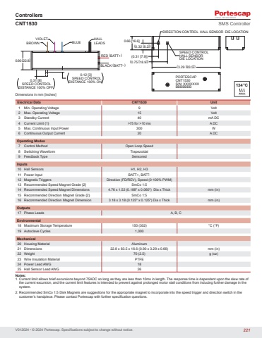
V012024 • © 2024 Portescap. Specifications subject to change without notice.ControllersDimensions in mm [inches]CNT1530 SMS ControllerElectrical Data CNT1530 Unit1 Min. Operating Voltage 9 Volt2 Max. Operating Voltage 15 Volt3 Standby Current 40 mA DC4 Current Limit {1} >75 for >10 ms A DC5 Max. Continuous Input Power 300 W6 Continuous Output Current 20 A DCOperating Modes7 Control Method Open Loop Speed8 Switching Waveform Trapezoidal9 Feedback Type SensoredInputs10 Hall Sensors H1, H2, H311 Power Input BATT+, BATT12 Magnetic Triggers Direction (FD/REV), Speed (0-100% PWM)13 Recommended Speed Magnet Grade {2} SmCo 1:514 Recommended Speed Magnet Dimensions 4.76 x 1.52 (0.188\mm (in)15 Recommended Direction Magnet Grade {2} SmCo 1:516 Recommended Direction Magnet Dimension 3.18 x 3.18 (0.125\mm (in)Outputs17 Phase Leads A, B, CEnvironmental18 Maximum Storage Temperature 150 (302) °C (°F)19 Autoclave Cycles 1,000Mechanical20 Housing Material Aluminum21 Dimensions 22.8 x 83.5 x 16.6 (0.90 x 3.29 x 0.66) mm (in)22 Weight 70 (2.5) g (oz)23 Wire Insulation Material PTFE24 Power Lead AWG 1825 Hall Sensor Lead AWG 26Notes:1. Current limit allows brief excursions beyond 75ADC so long as they are less than 10ms in length. The response time is dependent upon the slew rate of the current excursion, and the current limit features is intended to prevent against prolonged motor stall conditions from inducing further damage in the system.2. Recommended SmCo 1:5 Disk Magnets are suggestions for the appropriate magnet to incorporate into the speed trigger and direction switch in the customer’s handpiece. Please contact Portescap with further specification questions.(0.31 [7.9])(0.75 [18.9])(3.29 [83.5])(0.32 [8.2])0.66 [16.6]SPEED CONTROLHALL SENSORDIE LOCATIONDIRECTION CONTROL HALL SENSOR DIE LOCATION0.31 [8]SPEED CONTROLDISTANCE 100% OFF0.12 [3]SPEED CONTROLDISTANCE 100% ON0.90[22.8]BLACK (BATT–)RED (BATT+)BLUEVIOLETBROWNHALLLEADSPORTESCAPCNT1530S/N: XXXXXXXBBBBBBB 134°C221
