
Page 56 - Demo
P. 56
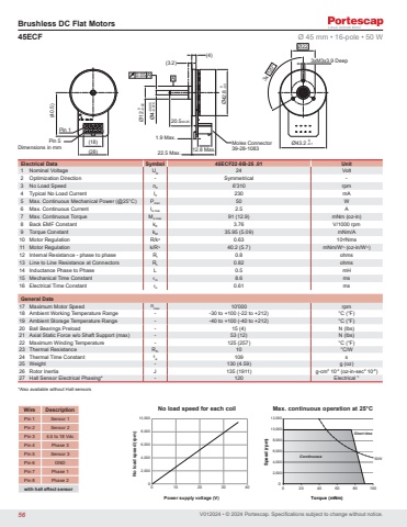
V012024 • © 2024 Portescap. Specifications subject to change without notice.Dimensions in mmBrushless DC Flat MotorsA 0.05 AØ20.5±0.2512 0-0.02Ø4-0.005-0.0100.1 Ø43.2 -0.1(40.5)Molex Connector39-28-10833x 120°3xM3x3.9 DeepØ22 0.1 Ø42.8 -0.3(4)(3.2)22.5 Max. 12.8 Max.1.9 Max.Pin 1Pin 5 (18)(28)45ECF Ø 45 mm • 16-pole • 50 W Electrical Data Symbol 45ECF22-8B-25 .01 Unit1 Nominal Voltage UN 24 Volt2 Optimization Direction - Symmetrical -3 No Load Speed n0 6'310 rpm4 Typical No Load Current I0 230 mA5 Max. Continuous Mechanical Power (@25°C) Pmax 50 W6 Max. Continuous Current Ie max 2.5 A7 Max. Continuous Torque Me max 91 (12.9) mNm (oz-in)8 Back EMF Constant kE 3.76 V/1000 rpm9 Torque Constant kM 35.95 (5.09) mNm/A10 Motor Regulation R/k2 0.63 103/Nms11 Motor Regulation k/R½ 40.2 (5.7) mNm/W½ (oz-in/W½)12 Internal Resistance - phase to phase RI 0.8 ohms13 Line to Line Resistance at Connectors RL 0.82 ohms14 Inductance Phase to Phase L 0.5 mH15 Mechanical Time Constant τm 8.6 ms16 Electrical Time Constant τe 0.61 msGeneral Data17 Maximum Motor Speed nmax 10'000 rpm18 Ambient Working Temperature Range - -30 to +100 (-22 to +212) °C (°F)19 Ambient Storage Temperature Range - -40 to +100 (-40 to +212) °C (°F)20 Ball Bearings Preload - 15 (4) N (lbs)21 Axial Static Force w/o Shaft Support (max) - 53 (12) N (lbs)22 Maximum Winding Temperature - 125 (257) °C (°F)23 Thermal Resistance Rth 10 °C/W24 Thermal Time Constant τw 109 s25 Weight - 130 (4.59) g (oz)26 Rotor Inertia J 135 (1911) g-cm2 10-4 (oz-in-sec2 10-6)27 Hall Sensor Electrical Phasing* - 120 Electrical °*Also available without Hall sensorsWire DescriptionPin 1 Sensor 1Pin 2 Sensor 2Pin 3 4.5 to 18 VdcPin 4 Phase 3Pin 5 Sensor 3Pin 6 GNDPin 7 Phase 1Pin 8 Phase 2with hall effect sensor 0 10 20 30 40 04,0002,00010,0008,0006,00012,000020 40 60 80 100Continuous 50WShort time08,0002,0004,0006,00010,000No load speed (rpm)Power supply voltage (V)No load speed for each coilSpeed (rpm)Torque (mNm)Max. continuous operation at 25°C56
