
Page 62 - Demo
P. 62
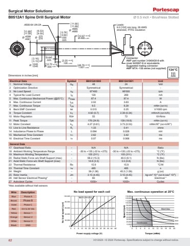
V012024 • © 2024 Portescap. Specifications subject to change without notice.Surgical Motor SolutionsDimensions in inches [mm][12.70 ±0.18].500 ±.007.4606-64 UN-2A[12.67 ±0.03]Ø.499 ±.0010.760.64.030.025[48.79 ±0.10]1.921 ±.00411.9011.89.4685 Ø .4680Ø3.163.15.1245.1240Connector:AMP part number 3-640430-8 with cover 643067-8 or equivalents. Suggested mating connector: AMP MTA -156 series (not supplied)Leads:6.0 [152] min long, 26 AWG stranded, PTFE insulation[3.20 ±0.05].126 ±.002[0.64].025Ø11.6811.58.4598.4561 Ø9.539.50.375.374B0512A1 Spine Drill Surgical Motor Ø 0.5 inch • Brushless SlottedElectrical Data Symbol B0512A1000 B0512A1001 Unit1 Nominal Voltage UN 48 24 Volt2 Optimization Direction - Symmetrical Symmetrical -3 No Load Speed n0 97'400 96'000 rpm4 Typical No Load Current I0 120 269 mA5 Max. Continuous Mechanical Power (@25°C) Pmax 87.4 87.4 W6 Max. Continuous Current Ics 2.02 3.63 A7 Max. Continuous Torque Tcs 9.5 8.28 mNm (oz-in)8 Back EMF Constant kE 0.515 0.25 V/1000 rpm9 Torque Constant kT 4.92 (0.7) 2.39 (0.34) mNm/A (oz-in/A)10 Motor Regulation R/k2 55 72 103/Nms11 Peak Torque Tpk 176 (24.9) 139 (19.8) mNm (oz-in)12 Motor Constant kM 4.27 (0.61) 3.73 (0.53) mNm/W½ (oz-in/W½)13 Line to Line Resistance RL 1.33 0.41 ohms14 Inductance Phase to Phase L 0.094 0.028 mH15 Mechanical Time Constant τM 2.62 3.42 ms16 Electrical Time Constant τE 0.07 0.068 msGeneral Data17 Gearhead Ratio - N/A N/A Ratio18 Ambient Working Temperature Range - -30 to +135 (-22 to +275) -30 to +135 (-22 to +275) °C (°F)19 Maximum Winding Temperature - 155 (311) 155 (311) °C (°F)20 Radial Static Force w/o Shaft Support (max) - 68.2 (15.3) 40.5 (9.1) N (lbs)21 Axial Static Force w/o Shaft Support (max) - 14.8 (3.3) 3.5 (0.8) N (lbs)22 Thermal Resistance Rth 15.9 15.9 °C/W23 Thermal Time Constant τw 485 485 s24 Weight - 39 (1.36) 45.2 (1.59) g (oz)25 Rotor Inertia Jm 3.15 (4.45) 3.15 (4.45) kg-cm2 10-4 (oz-in-sec2 10-6)26 Hall Sensor Electrical Phasing* - 60 60 Electrical °27 Autoclave Cycles - 1000+ 1000+ CyclesWire DescriptionBlue Phase ABrown Phase BViolet Phase CRed 4.5 to 24 VdcYellow Sensor 1Orange Sensor 2White Sensor 3Black GND134°CB0512A1001B0512A10000 4 8 12 16 20 24 28 32 36 40 44 48 090,00080,00070,00060,00050,00040,00030,00020,00010,000120,000110,000100,000130,00002 4 6 8 10 12 14 16 18 2080W50WContinuous 25WShort time080,00020,00040,00060,000100,000No load speed (rpm)Power supply voltage (V)No load speed for each coilSpeed (rpm)Torque (mNm)Max. continuous operation at 25°C*Also available without Hall sensors62
